What is a loop resistance test?

A loop resistance test is carried out during aircraft manufacture or maintenance to check that it will be safe in the event of being struck by lightning.
Why are loop resistance tests needed?
Planes are struck by lightning about once a year*, based on data from the US Federal Aviation Authority (FAA). That’s surprisingly often isn’t it? It happens much more frequently than most people would assume.
The good news is that standard aircraft are designed to handle lightning strikes. A low resistance path is built into the design, enabling the lightning current to flow from the point of impact through to the tail of the plane where it can safely exit.
So, the principle behind the design is simple enough. However, a single high resistance joint can hinder the route of the lightning current, possibly resulting in catastrophe.
What can go wrong with a high-resistance joint?
Correct electrical bonding is critical in ensuring the safety of aircraft and passengers. As already mentioned, a single high-resistance joint is all it takes to render a lightning strike protection circuit useless.
Worse than that, the high-resistance joint becomes the focus of up to 200kA of lightning current trying to escape, which can lead to catastrophe.
High-resistance bonds can be caused by of the following reasons – and there are many more:
- Surface contamination
- Bonding surfaces being incorrectly prepared
- Missing components
- Faulty materials
- Loose crimps
- Loose ring terminals
- Incorrectly rated bonding straps
Aircraft are intricate mechanical and electrical assemblies; there are thousands of bonding points and ground circuits which need to be tested to ensure a low resistance path. A loop resistance test is therefore essential, but it can be time consuming and complex.
What is tested during a loop resistance test?
The various elements that combine to provide a low resistance path for the lightning strike to follow are called a bonding circuit. These elements are a combination of aerostructure sections, flight equipment housings/casing, cable harness shields, piping systems and bond straps.
It is the complexity of these elements that makes the efficacy of the testing method and validation of test results so important.
What’s the best bond and loop resistance test method?
Simple electrical bonds between two separate elements are relatively straightforward to test. Applying the Kelvin measurement principle, bond meters will cause a current to flow between the two elements, measure the volt drop across the bond, and report the resistance.
Is the Kelvin measurement principle appropriate for all circuits?
This method is not suitable when it comes to testing circuits containing parallel paths; despite this, bond meters are still frequently – and incorrectly – used in this scenario.
To explain why this is, take the below illustration (figure 1) as an example. The two sections of aircraft structure are connected by a series of bonding straps; one of the bonding points has been badly assembled and is an open circuit.
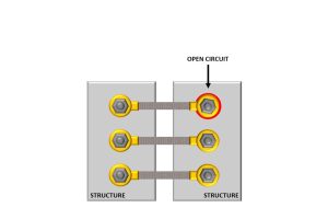
Figure 1
If this assembly is tested using the bond meter described above, the parallel resistance paths allow the current to flow between the meter’s probes. The volt drop is measured but that volt drop is through the parallel bond straps. The resulting measured resistance is therefore a sum of the parallel resistance paths, enabling the test to inadvertently record a pass result when it should have failed.
In the event of a real-life lightning strike current flowing through this system, there would be up to 200kA forced across the joint – with likely catastrophic results.
Types of loop resistance testing tools available
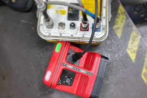
The most effective loop resistance test method is with a purpose-designed tool, such as the legacy ‘LRT’ as well as MK Test Systems’ range of tools.
These tools all use the same technique of injecting a current into the loop using clamps (or ‘couplers’). The current is then measured as it flows through the loop. The voltage required to cause the current to flow is monitored, and the impedance of the loop is calculated.
Phase correction is applied to isolate the resistive element, and to report the resistance of each individual loop.
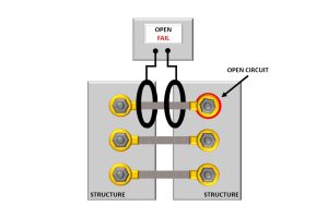
Figure 2
In the example shown above (figure 2), the loop test system would report the loop as an open circuit, enabling engineers to correct the fault.
OEMs have various requirements when it comes to loop resistance testing. Maintenance operators should always check the AMM to ensure the appropriate tool and methodology is being used.
Want to learn more?
We offer a range of bond and loop test tools, suitable for a variety of applications:
ExLRT is our intrinsically safe loop resistance tester designed for use in MRO environments. It’s over 80% lighter than the industry standard LRT, and it’s listed in Boeing maintenance manuals as an approved tool. Visit the ExLRT product page here.
BLRT is a fully automatic bond, loop and joint resistance tester with built-in operator instructions. It speeds up the testing process by diagnosing faults quickly, and automatically uploads results to production systems once all checks have passed. Recommended by Boeing for testing bonds, loops and joints during the manufacture of aircraft and aircraft subassemblies. Visit the BLRT page here.
BLTU4 is suitable for use on Airbus aircraft. It’s an automatic, portable bond and loop resistance tester which also has operator guidance. The BLTU4 provides automatic testing of ground bonding points on aircraft and other large structures and records the test data for full traceability. Visit the BLTU4 product page here.
If you’d like to find out how our ExLRT and BLRT models compare to the legacy ‘yellow box’ LRT (model 906-10246-3), then our comparison article is worth a read.